Central Heating System Diagram
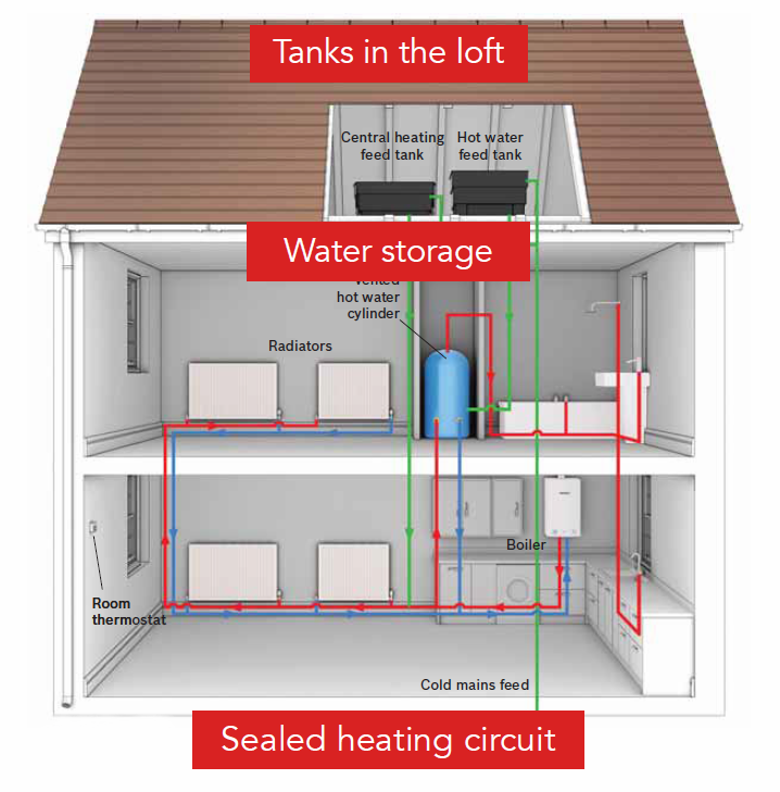
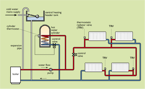
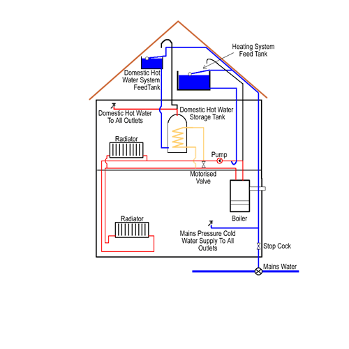
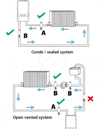
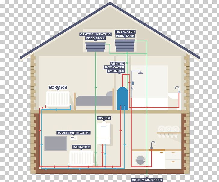
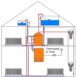
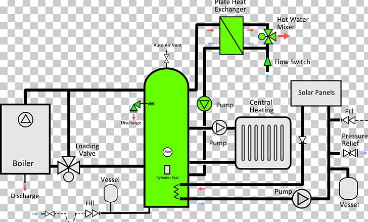
Central heating system diagram. The open vented system is fed from a feed and expansion tank located in the loft this keeps the system topped up and also allows the water to expand as it heats up. The diagram set includes wiring plans for a number of popular configurations of central heating systems c plan w plan y plan s plan s plan etc. Why Understand the HVAC System Diagram.
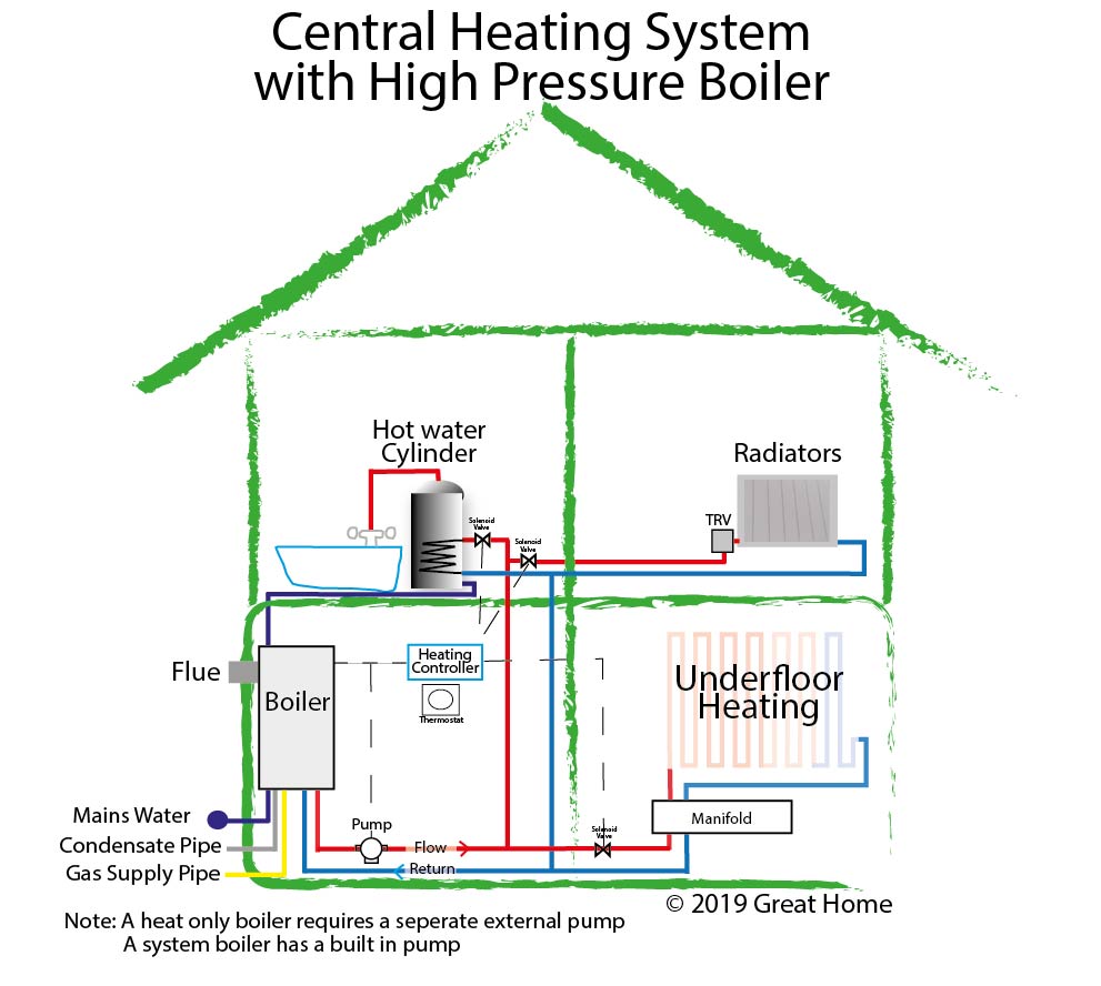
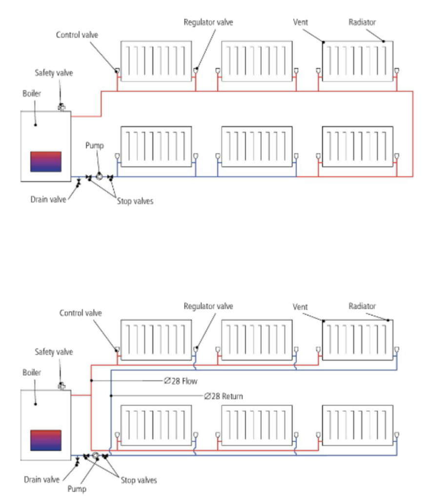
In domestic central heating systems the most common pipe sizes are 28mm 22mm and 15mm. NOTE A pump must be installed in the hot supply line between the outdoor furnace and thermostatic valve. The diagrams below show three central heating types.
Interconnecting wire routes may be shown approximately where particular receptacles or fixtures must be upon a common circuit. Architectural wiring diagrams acquit yourself the approximate locations and interconnections of receptacles lighting and enduring electrical services in a building. This type of system operates at mains water pressure and uses a stored hot water system.
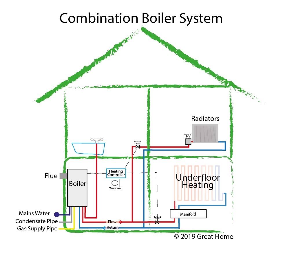
Showing flow from boiler to Y Plan or Mid Position Diverter Valve and then onto heating or hot water circuit. It shows how the tank boiler and pipes ensure a constant flow of hot water to both the radiators and the tapsu003cpu003ennu003cpu003eThe cold water enters the house and is stored in a water. Combi Boilers are modern boilers that are responsible for both the heating and hot water in the home.
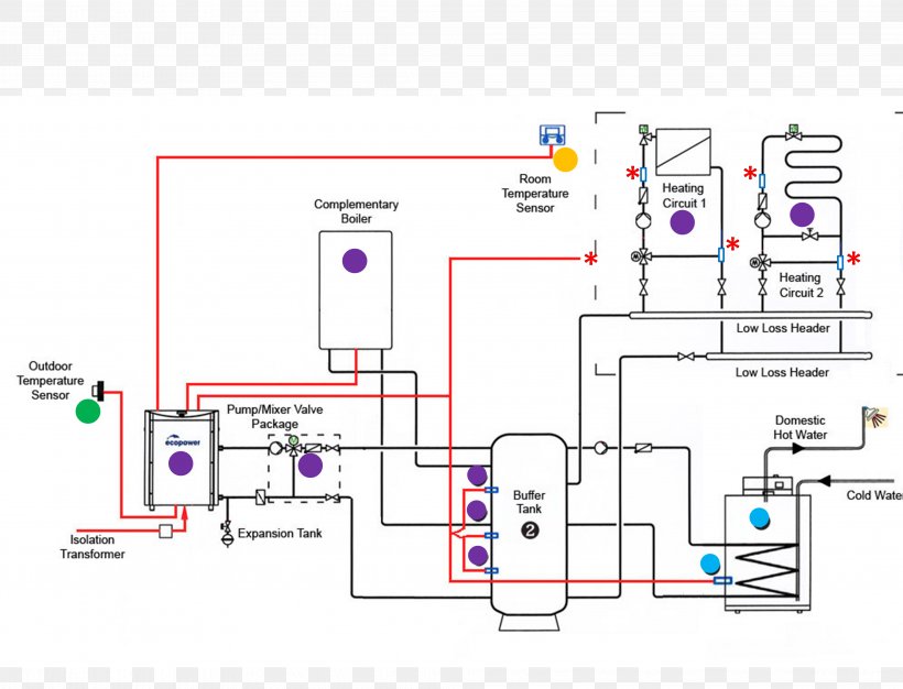
System Diagrams H C M R Thermostatic Valve optional NOTE Outdoor furnace water temperature setpoint should be set at 185F minimum. Download central heating system diagram uk pdf Add or remove Preferred Care for this device to match what s already in your cart or buy this device in a separate order. Part 4 in the heating wiring series covers how the 3 port mid position valve works internally allowing 3 separate positions from only 2 mains inputsWebsite.
Pipes for central heating systems can be either copper or plastic and come in many sizes from 8mm to 35mm in diameter. The vented boiler regular boiler and combination boiler systems probably account for over 95 of water-based central heating installations. This is then diverted from the central heating circuit to go into the water to the heat exchanger where it passes the heat from the central heating water to the cold water coming into the boiler.
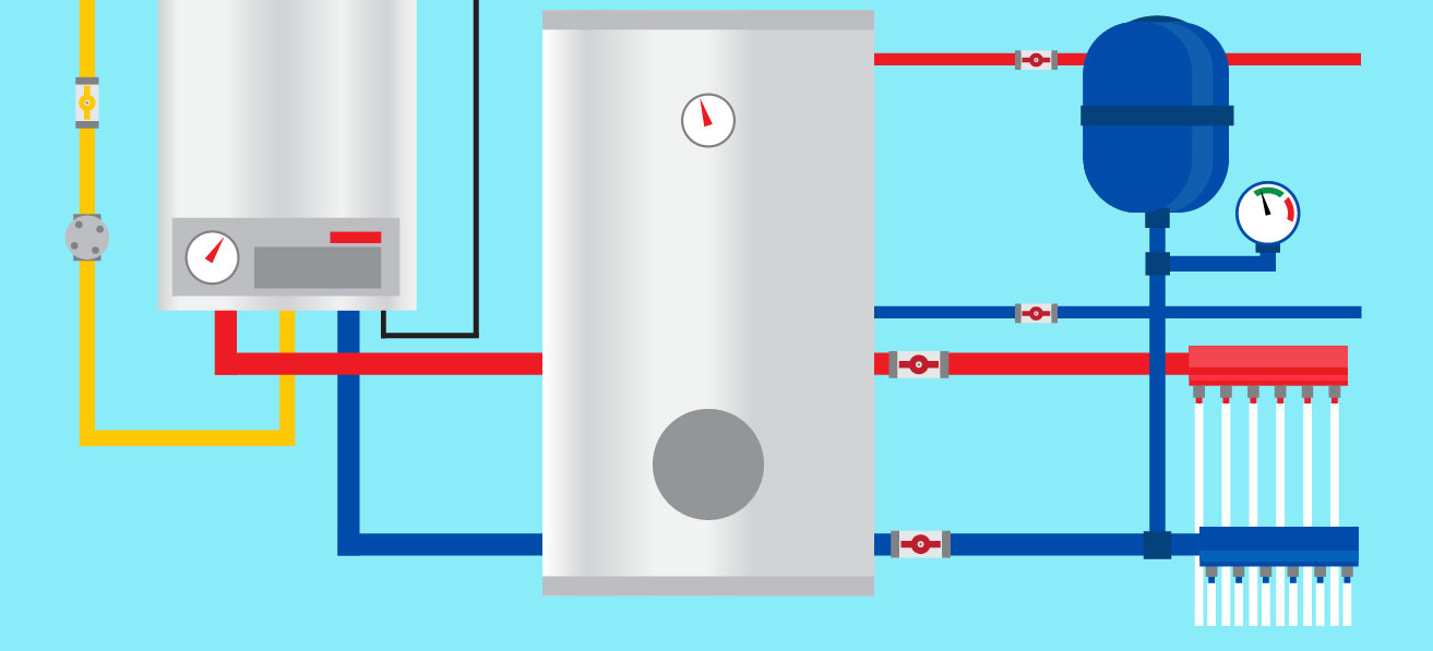
Existing Boiler Hot Supply 1 Central PEX This horizontal assembly must not exceed a height of 4 inches above top of water heater. The type of pipework used in a system is dependent upon a number of factors.
This is then diverted from the central heating circuit to go into the water to the heat exchanger where it passes the heat from the central heating water to the cold water coming into the boiler.
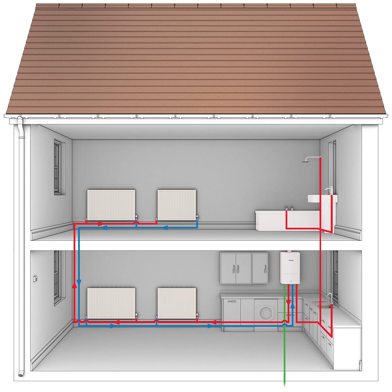
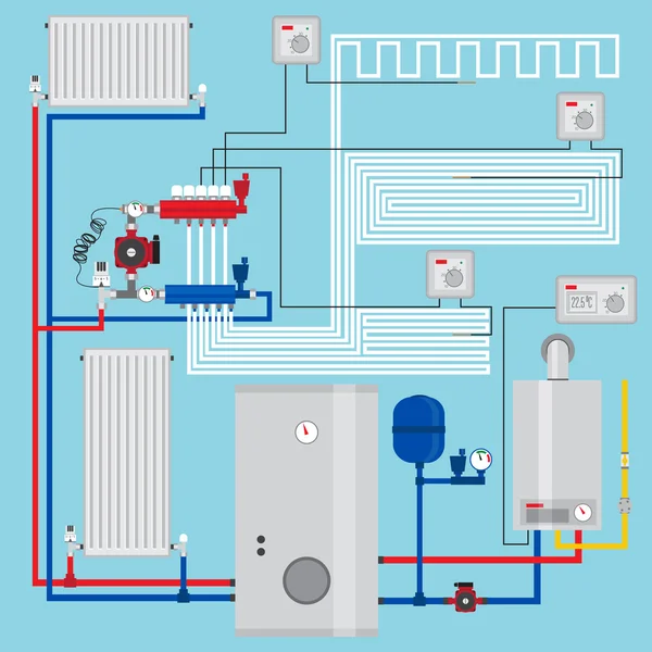
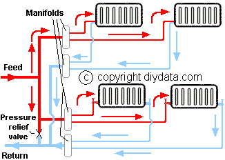
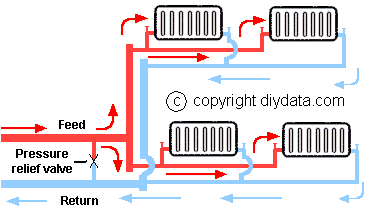
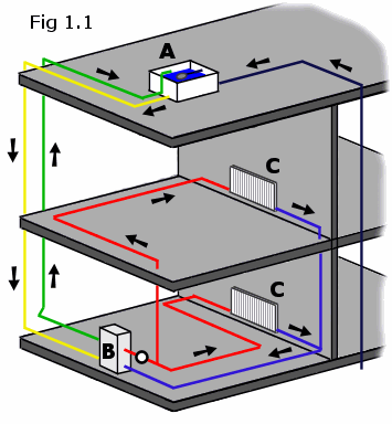
Honeywell wiring diagram y plan full how a heating system works s central w evohome ing diynot forums does an work sundial pack 7 day with greenstar worcester boiler coloured scheme for Diagram Honeywell Wiring Y Plan Full Version Hd Quality Diagrampress Reverbfestival It How A Y Plan Heating System Works Design Boiler Boffin. Single pipe - feed and return - micro bore. Whether you are learning more about how your compressed air system works optimising how your vacuum pump works or looking to increase your compressor energy efficiency find out tips that will benefit you. Id2241titlenulladvertisement_flagfalseauthor_id1contentnu003cpu003eThis diagram provides an overview of a domestic central heating system. System Wiring Diagrams. The diagrams below show three central heating types. An APHC member can provide advice and guidance on the best. A guide to the most common types of domestic heating and hot water systems with diagrams including indirect boiler system unvented system thermal store. The three main boiler types found in a wet central heating system are Combi Boilers System Boilers and Regular Conventional Boilers.
A guide to the different ways of heating domestic hot water so you can identify problems and faults with the hot water tank or central heating system and carry out any maintenance needed. The three main boiler types found in a wet central heating system are Combi Boilers System Boilers and Regular Conventional Boilers. The boiler heats the water and normally a pump circulates the water through the pipework and radiators and back to. Interconnecting wire routes may be shown approximately where particular receptacles or fixtures must be upon a common circuit. A water central heating system consists of basically the boiler the radiators and the interconnecting piping. Download central heating system diagram uk pdf Add or remove Preferred Care for this device to match what s already in your cart or buy this device in a separate order. We can keep your temperature steady.

















Post a Comment for "Central Heating System Diagram"